Is there any way to simplify the configuration and maintenance of a Hub and Spoke topology using the upgraded DRG? Do we have any default configuration that will make this design to work with a minimum effort? What is the difference between Hub and Spoke configuration from legacy DRG to upgraded DRG?
Welcome to our new blog post! We will describe how easy is to setup a Hub and Spoke topology using the upgraded DRG.
For having a clear difference between H&S configuration we will analyze two types of topologies, the legacy one, using the kegacy DRG and we will migrate the same topology but using the new upgraded DRG capabilities. We will focus on the minimum configuration that needs to be applied for the traffic from On-premise to OCI and vice-versa to work.
Networking Topology for Legacy DRG Hub and Spoke
Note: The upgraded DRG is backward compatible with the legacy DRG. Also, the above Hub and Spoke LPG configuration is supported by the upgraded DRG. The upgraded DRG is adding more routing features compared to the legacy DRG.
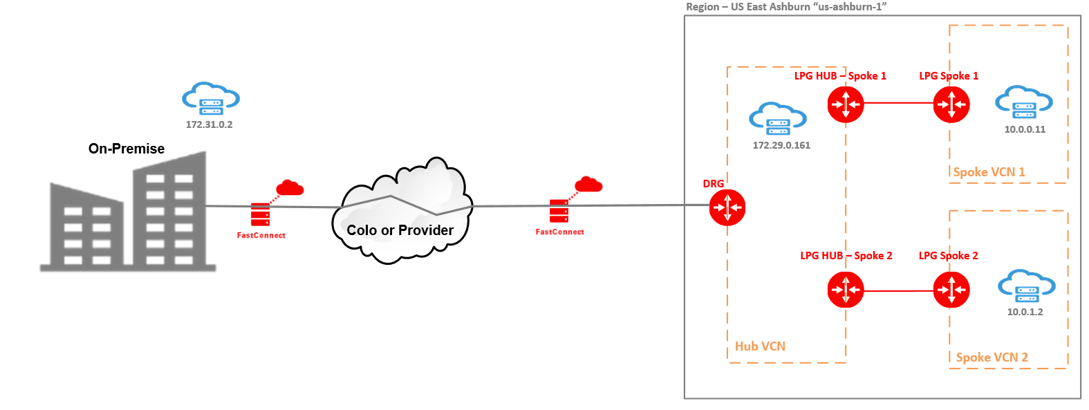
Above we have a traditional Hub and Spoke topology using LPG to connect from Hub VCN to each Spoke. The connectivity to On-premise is created using a FastConnect Virtual Circuit but an IPSec tunnel can be used instead.
In our example we will use the upgraded DRG because the it is backward compatible with the legacy DRG. We will not use any upgraded DRG new feature, we will just implement the Hub and Spoke in the legacy DRG fashion.
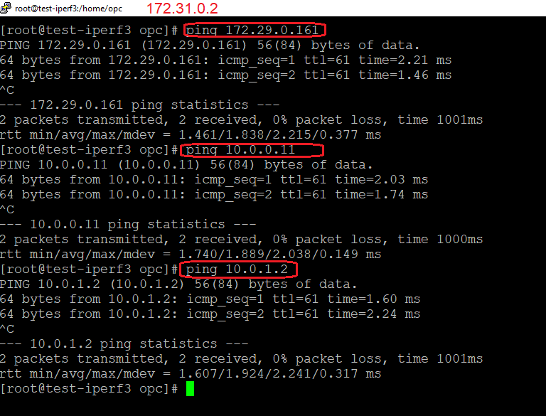
For testing the connectivity we are using an On-premise VM at 172.31.0.2, another VM placed in the Hub VCN at 172.29.0.161 and two VMs in each Spoke VCNs at 10.0.0.11 respectively 10.0.1.2. The scope is for On-premise VM to be able to access all three VMs on OCI.
Configuration Steps
1. Attach the Hub VCN to the DRG;
2. In the Hub VCN create two LPGs, one will peer with Spoke 1 and the second one with Spoke 2;
3. In each Spoke VCNs create an LPG;
4. Create an LPG relationship from Hub LPGs to each Spoke LPG;
5. In the Hub VCN create one dedicated LPG Route Table and attach the Route Table to each of the LPGs (assuming we have the same routing requirements for both Spoke VCNs);
6. In the RT from step 5, add a route to On-premise 172.31.0.2/32 with the DRG as next-hop;
7. In the Hub VCN create one dedicated DRG Route Table and attach the Route Table to the DRG;
8. In the RT from step 7, add one route to Spoke 1 VM with the LPG HUB – Spoke 1 as next-hop and a second route to Spoke 2 VM with the LPG HUB – Spoke 2 as next-hop ;
9. In the Hub subnet where 172.29.0.161 sits, add a route to 172.31.0.2/32 with the DRG as a next-hop and make sure the Security List or NSG associated permits the traffic to/from 172.31.0.2;
10. In the Spoke 1 subnet where 10.0.0.11 sits, add a route to 172.31.0.2/32 with the Spoke 1 LPG as a next-hop and make sure the Security List or NSG associated permits the traffic to/from 172.31.0.2;
11. In the Spoke 2 subnet where 10.0.1.2 sits, add a route to 172.31.0.2/32 with the Spoke 2 LPG as a next-hop and make sure the Security List or NSG associated permits the traffic to/from 172.31.0.2;
Traffic Testing
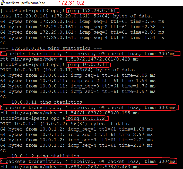
On-premise to OCI:
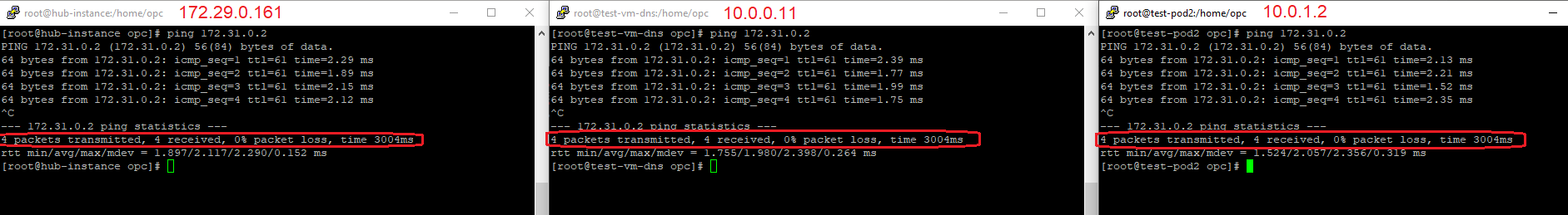
OCI to On-Premise:
As we can see, to achieve the bidirectional traffic we need to follow the 11 steps above for a setup with only two Spoke VCNs. If the number of Spokes will increase (no more than 20 as a hard limit), we need to increase our configuration efforts as well.
Let’s check if we can simplify our configuration efforts with our upgraded DRG routing capabilities.
Networking Topology for Upgraded DRG Hub and Spoke
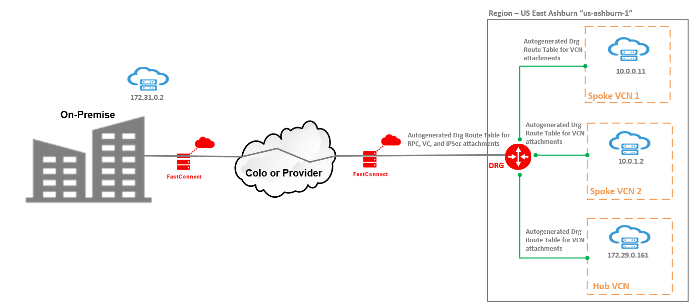
With the upgraded DRG we can attach up to 300 VCNs so, the DRG itself becomes a Hub. There is no need in the default configuration to define a specific Hub VCN. In our scenario, we have two types of DRG attachments, VCN attachments and FastConnect VC attachments.
A default configuration automatically applied is to define for each type of attachment a specific Route Table used for routing the traffic to specific destinations once the traffic is received over the attachments.
For VCN attachments, the Route Table applied is called: Autogenerated Drg Route Table for VCN attachments.
For FastConnect attachments, the Route Table applied is called: Autogenerated Drg Route Table for RPC, VC, and IPSec attachments.
The Route Table for VCN attachments is importing all the routes, received on all the attachments.
The Route Table for FastConnect VC imports only the VCN routes – so, the VCN CIDRs are sent to On-premise in BGP advertisements and on another hand is used for routing the traffic to specific VCN VMs once the traffic is received from On-premise and the destination is a VM from an attached VCN.
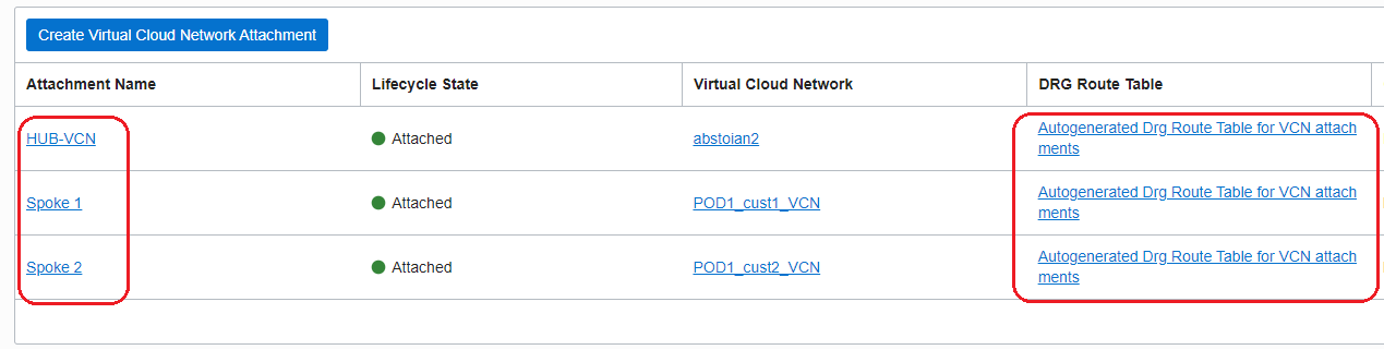
The VCN attachments are listed in the below picture:
Configuration Steps
1. Attach the Hub VCN to the DRG;
2. Attach the Spoke 1 to the DRG;
3. Attach the Spoke 2 to the DRG;
4. Make sure that all the subnets have a route to 172.31.0.2/32 with the DRG as a next-hop and the Security Lists or NSGs permits the traffic to/from 172.31.0.2/32;
Traffic Testing
On-premise to OCI
OCI to On-premise
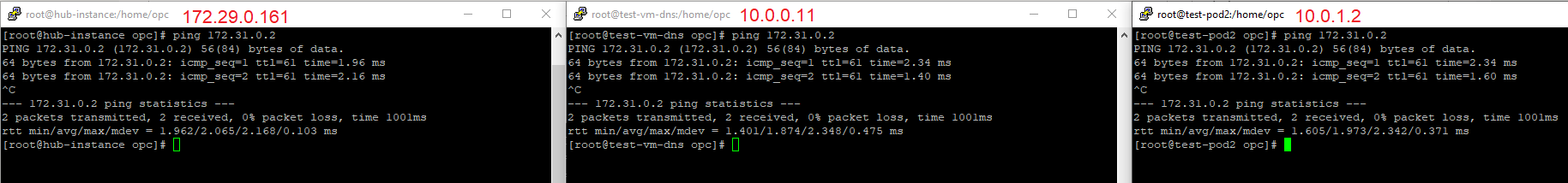
The traffic is working in both directions and we have achieved it in only four steps compared to legacy DRG.
This is the default configuration that we need for basic connectivity between On-premise and OCI when multiple VCNs are attached.